How to build “iPrzedluzacz” – the ultimate internet enabled desk power source
Sometimes people do things just because they don’t want to do other things they supposed to do, for example when you should learn for the exam you usually start cleaning your room etc 🙂 This is exactly the project of this kind. When I was looking for smth in my old stuff I’ve found an Arduino Mega I bought a couple of years ago and I had decided that its a good time to do something with it. Below its a simple recipe on how to build your own Arduino powered, internet enabled power source. The main idea behind this project is to be able to control 8 hight voltage endpoints using an internet, on the way I thought it would be nice to measure the mains voltage and current to calculate the power usage by all 8 endpoints together. On top of it I had added a simple 1-Wire temperature sensor to get the temperature information as well.
What will you need:
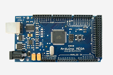
- An Arduino, I have used an Arduino Mega but it all depends how many relays you want to control, Mega contains a plethora of pins you could use for analog and digital inputs/outputs, I2C, PWM and whats not. I guess you could easily go with a smaller Arduino but the choice is yours of course.
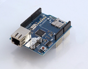
- Arduino Ethernet Shield – this is in case you want to connect the stuff to internet which you want of course, there is of course a much nicer way with WiFi instead of Ethernet but it all depends what you have already in your toolbox and how much money you want to spend.
 2. Relay board with as many relays as you need, I have the version for 8 relays, 230V and max 10A each.
 3. Power source – I have used a power adapter I had found from my old UK DAB radio, cut it open and extracted the PCB with all needed components, it gives me 6V and about 2A which is enough to run all the gear I need.
4. A transformer – this is to measure mains voltage, I have used one from old Nokia charger, gives me 9V, the amperage doesn’t matter here.
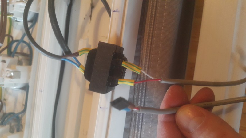
 5. A current sensor. I have used the one for 100A which I had available but it gives me problems (more on that below). There is another version of this sensor for 30 Amps which you should, I guess for smaller loads it would be more precise but who knows.
 6. Temperature sensor, for accurate readings and because I had I2C available I used popular DS18B20 sensor
7. Any LCD Display
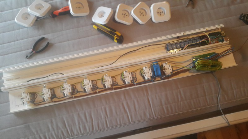
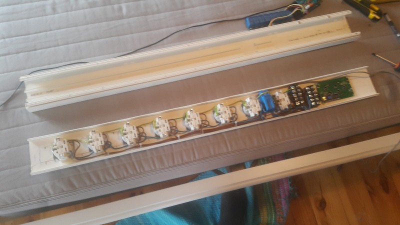
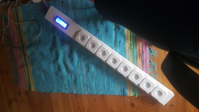
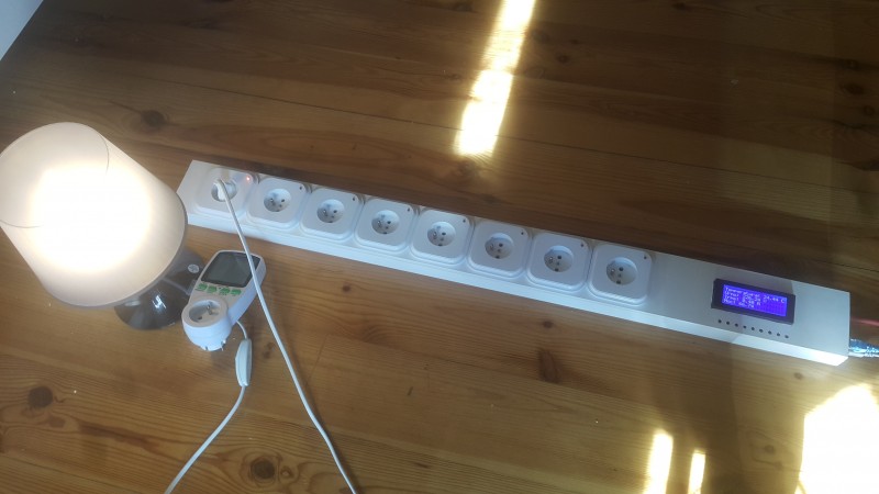
Finished product looks like the one below:

by executing the commands on the PC terminal or directly in the browser I’m able to switch on and off the 8 plugs with power as well as receive the status update from the thing itself with information which relays are on/off, the current temperature, voltage and amperage used.
Driving relay shield is pretty straightforward and I’m not going to describe it here in more detail, just have a look into the source code available on github (link given) and you should be fine. Whats interesting (a bit more) is current and voltage reading. While I was working on this project I have found an excellent resource for the power measurements at: openenergymonitor.org
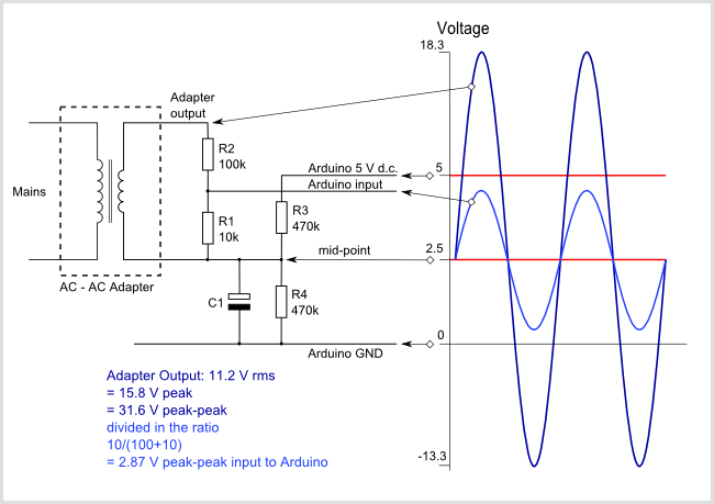
Reading voltage:
I was lucky enough to find similar adapter they used on the OpenEnergyMonitor, it actually just a transformer I have managed to get out of old sealed Nokia charger, it gives me around 9V and was equipped with a simple Gretz bridge I got rid off. I have connected it to the Arduino in a similar way given here:
Reading current
Similarly, current measurement was done with the SCT-013-000 sensor (https://nettigo.pl/products/bezinwazyjny-czujnik-natezenia-pradu-ac-max-100a) there is an 30A option available which could I guess give a better accuracy with smaller loads (not sure about that tho).
Full description on how it works is given here

Ok, now we have two simple circuits with a couple of capacitors and a small number of resitors which we need to connect in more reliable way than in a wire-spider-thing on your desk. For that purpose I have managed to create a simple PCB layout which is available on the same github repository as the source code for the Arduino itself. I have used popular toy tool called Fritzing.

I added a bit more pins for Vcc and Ground as well as 3-pin connector with single resistor for temperature sensor. J1 connector with CS and VS labels is the one which should be connected to the Arduino analog inputs for current and voltage readings respectively. Not-so-state-of-the-art PCB (single layer) looks like the following:

and its 44x31mm big.
The IRms, VRms, Wattage and all other measurements are done with the usage of EmonLib library found on OpenEnergyMonitor website.
Reading temperature
The temerature is read with the very popular DS18B20 sensor which uses 1-Wire protocol to communicate with Arduino, again its so simple and straightforward that I’m not going to write more about it here.
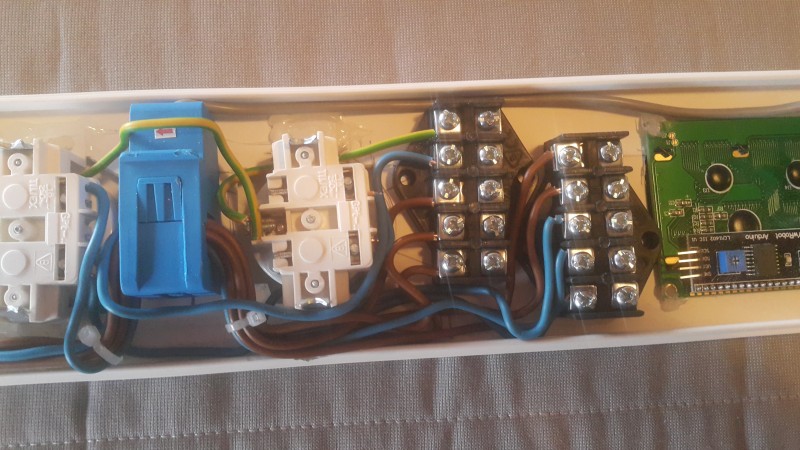
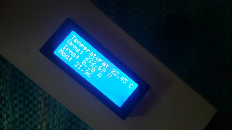
LCD Display

I have used nice and shiny 4×20 blue LCD where I show current temperature, Vrms, Irms and calculated Wattage. The code given on github is able to show more screens with currently set MAC address and IP of the device itself.
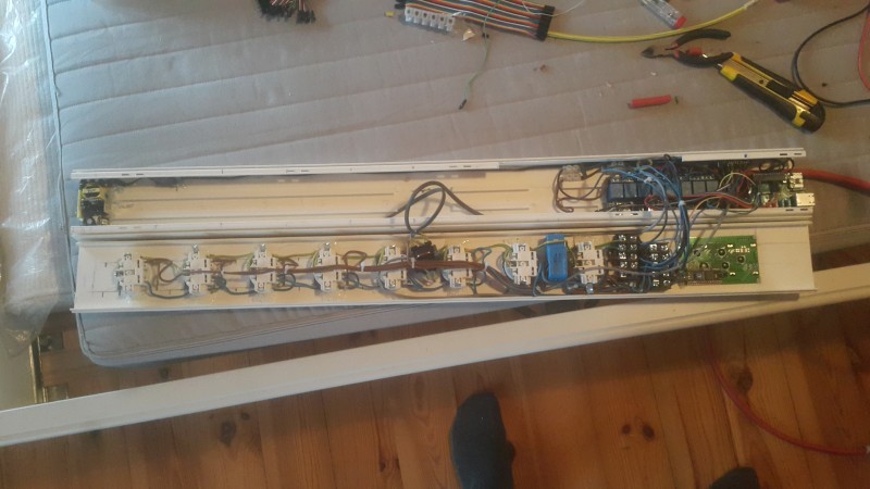
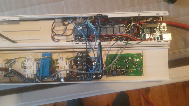
Putting it all together
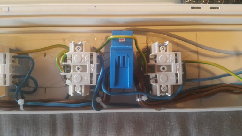
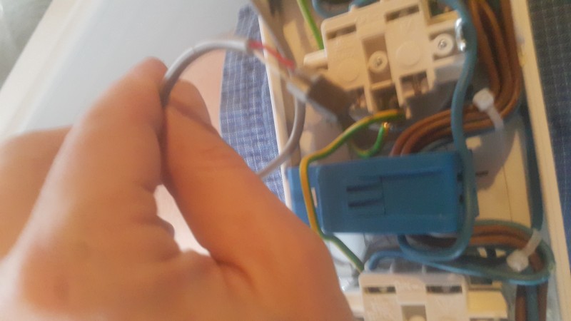
Once all the hardware is ready all we need to do is to wire it and put it in some kind of enclosure. I have used a simple thing from electrical shop used normally for hiding cables on walls (no idea whats the english name for it) you can buy it in many shapes and sizes and looks like its durable enough. Of course you need to wire the plugs with appropriate cables depending on amperage you expect there and you need to do it well to minimize the fire or electrical shock hazard, you need to remember that you work with possibly dangerous mains electricity. You have been warned.
Handling commands
At the moment the Arduino code allows:
- reading the relays state with HTTP GET request executed on the endpoint eg.
curl http://192.168.1.177/digital/get/7
- setting the relay state with
curl http://192.168.1.177/digital/set/7
- sending the status of the whole device with Temperature, IO states, Irms, Vrms to the remote server (have a look into the code itself for more details)
All of this communication is handled with simple HTTP requests and will be replaced by publish-subscribe mechanism with MQTT soon.
Known problems
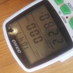
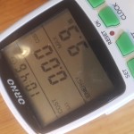
There is a problem with accuracy of the current sensor, I believe that its caused by high amperage it can support but I’m not sure tho. I’m still investigating that, at the moment its really sensitive to the environment around it and the measurements change slightly even when the relays are switched. I do compare it to the power meter I bought cheap from the DIY store and so far the cheap Chinese version wins 😉

Unknown future
Recently I have added LEDs to each plug to see which one is exactly on cos once the enclosure is closed and the relay leds are not visible its difficult to say :). The diodes are not on the electrical diagram as I just wired them up to the arduino directly and they are drive by the LOW state similarly to the Relay board itself.
At the moment the Arduino code is a bit messy and its using simple GET type HTTP requests to send/receive its commands. This will be changed into MQTT mechanism with publish-subscribe way of doing things in the near future. Another thing is adding small push buttons directly on the enclosure so I don’t need to have an internet to switch the damn thing on or off :).
Because the ethernet shield is coming with the SD card reader I guess it won’t be much of a hassle to save the state of the relays and switch the same ones on when the power goes off/on.
Github repository for lost souls is here
If you have any suggestions, of course you can leave the comment below.