iBirdFeeder – Part I – Hardware
The semi-automatic seed transporter
The first thing I was planning to build was the seed transporter, the reason is, it was the biggest unknown in the whole project and to the end I didn’t have a clear idea how am I gonna build it. I have decided to use a simple wood drill and a plastic pipe (I guess the pipe is normally used for standard plumbing works, both the pipe and the drill are easily available in any hardware store. The idea is of course to provide the seeds on one side of the drill and by turning the drill, move it to the end of the pipe. The drill itself is quite heavy and it needs to turn quite slow so I needed to find an electric motor with high torque and small RPM which to my surprise wasn’t that difficult: https://nettigo.pl/products/maly-silnik-6v-z-przekladnia-1-60. The motor has a gear ratio of 1:60 and works with 5V easily.

To connect together the drill and the motor I have used a piece of wood with appropriate holes on each side and glued everything together


The drill needs to be of course a couple of mm smaller in diameter than the pipe inside to allow easy rotation. It turned out during initial tests that the difference in diameter of both elements is crucial to proper operation of the transporter as the seeds could block the drill when they got stuck between the side of the pipe and the drill itself (as the seeds are normally quite hard the motor could not handle to crash them)

Of course the length of the motor-drill assembly should be the the same or a bit bigger than the length of the pipe itself.


I have used a plastic cup where I can easily mount the motor and simple transistor circuit to switch the bigger current than the one available from the Raspberry Pi output pin.


As mentioned earlier, to run the motor from Raspberry Pi you need to switch the power through the transistor, I guess any transistor (npn, pnp) will do depending which state of the RPi output you want to use, I have used a BC54B NPN transistor with 8.2k resistor attached to its base (won’t go into details, use whatever you have available)

I have decided (just for a bit more fun) to equip the iBirdFeeder with temperature sensor (DS18B20)

The assembled unit looks more or less like the one below. We end up with 3 wires: +5V, GND and the one to turn the motor on with high signal from the RPi. Just more or less where the wooden adapter ends the seeds are coming through the hole from the bigger container at the top. The whole pipe gets mounted with an angle so the seeds basically could go down the pipe with gravity but the drill stops them from moving. Once the drill gets moving the seeds are transported down the pipe and onto the small deck available on the wooden base of the birdfeeder (see the photos at the end for the fully assembled birdfeeder to get the idea)

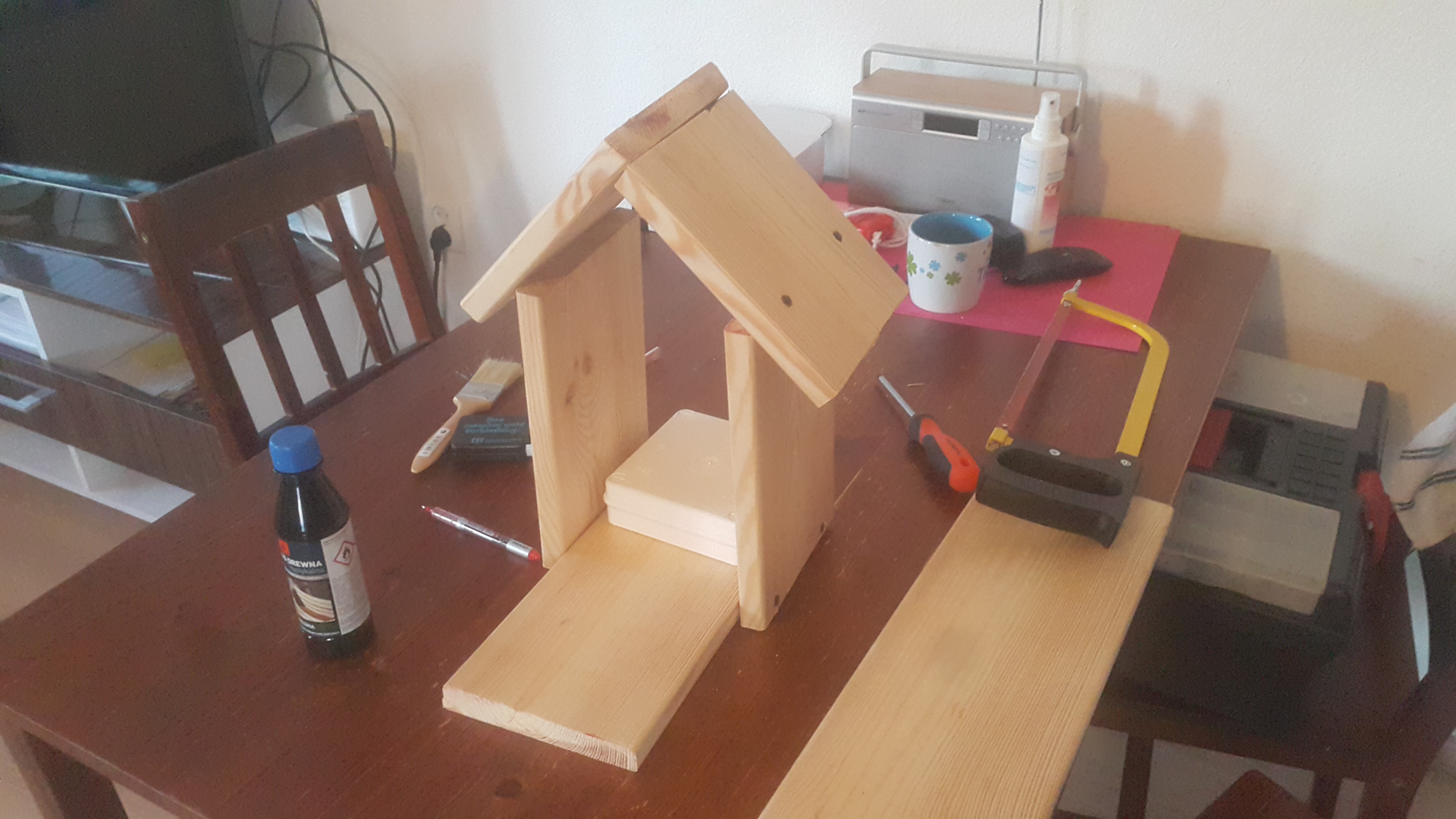
Now the woodwork! As you can easily see for the following photos I’m lacking the carpentry skills J or maybe more the proper tools 😉
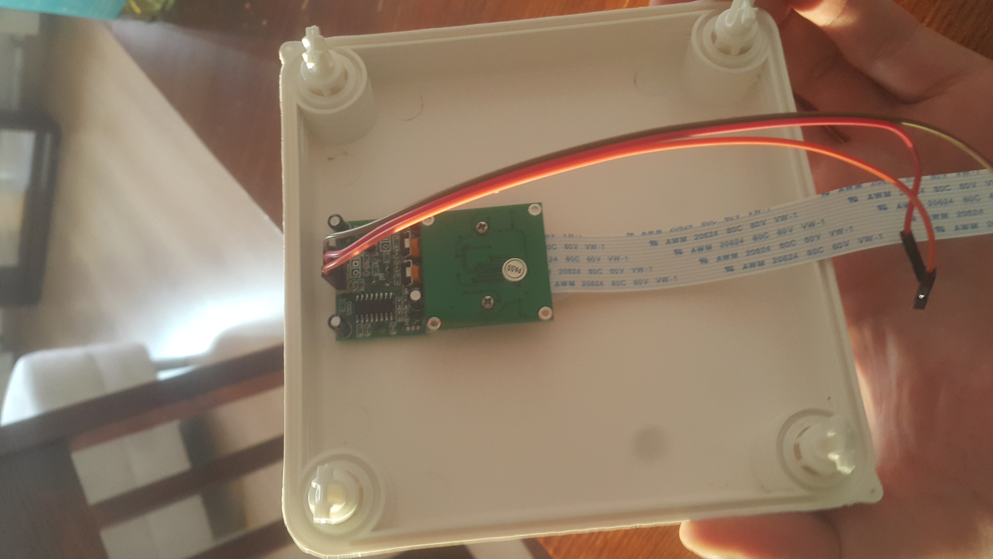
For the Raspberry Pi + PIR sensor + camera case I have used some simple plastic box found in hardware store (normally used for electrical purposes). You can find many different shapes and sizes plus moisture resistance and pick the one which suits you best, of course you need to remember that it needs to be large enough to hold all 3 modules in place.
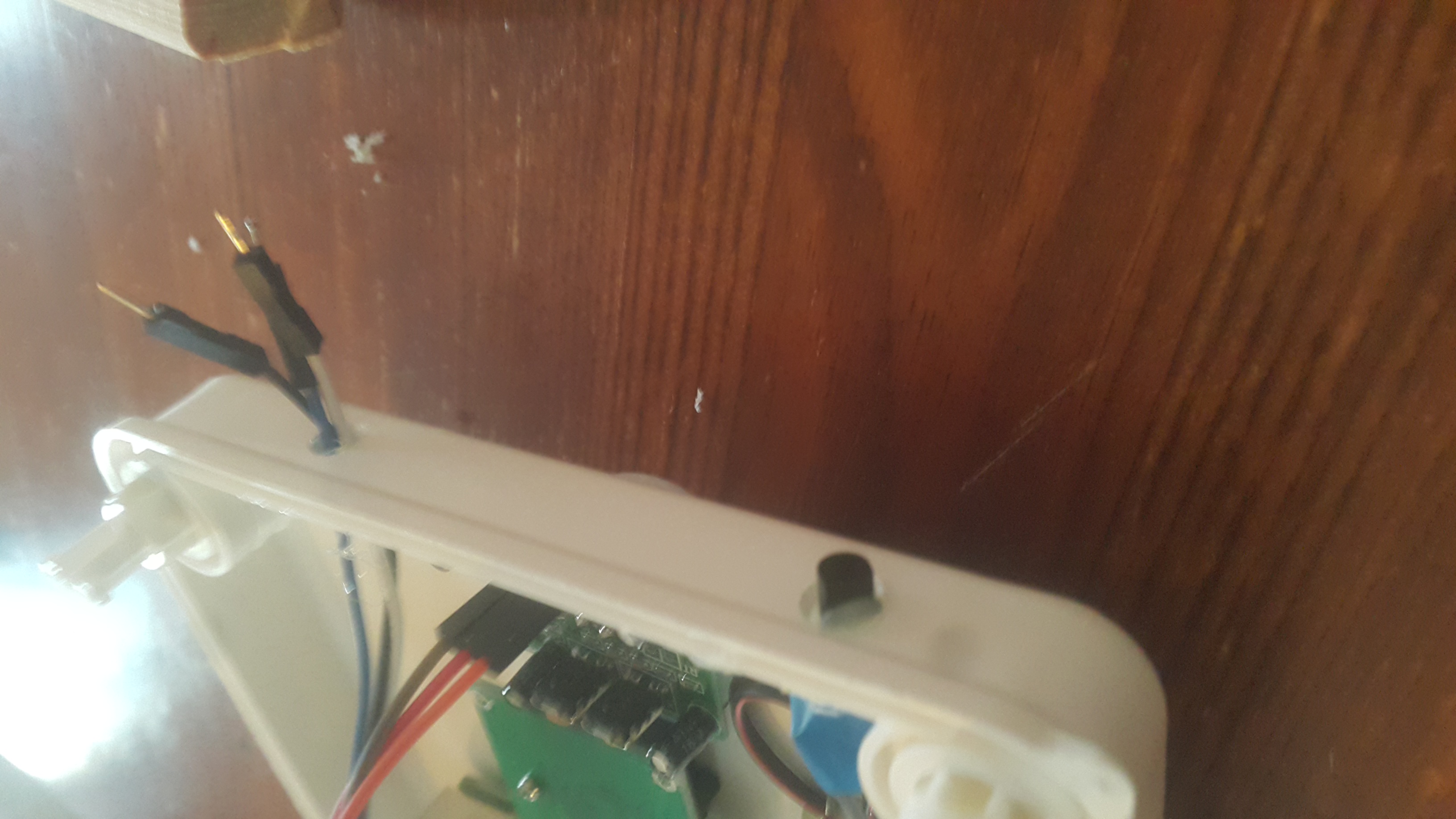
Assembled camera module and PIR (front)

Assembled camera module and PIR (back)
RPI + PIR + Camera + DS18B20 temperature sensor (inside)

For the motor feeder wiring, temperature sensor and power input I have drilled additional holes in the case which after assembly I filled with hot glue to keep the whole case moisture resistant.


Assembled RPi case with USB cable mounted inside for power input.

Whole bird feeder assembled together and after paint work. The deck where the seeds land was later changed for a different one with more ‘plate-like’ shape to keep the seeds in the middle.


I have attached the small pipe to the PIR sensor to limit its range of operation to a smaller angle . It turned out that its picking up signals from all around instead of just the front of the bird feeder where the seed deck is mounted.

Final bird feeder installation on the roof of my house.

For the specific pins used on Raspberry Pi 3 board itself please look into the next part of the BirdFeeder series when I write about programming RPi itself.